In commercial construction and architectural building envelope design, thermal efficiency and solar control are critical determinants of energy code compliance, HVAC equipment sizing, and long-term operating costs. Model energy codes—such as the International Energy Conservation Code (IECC) and ASHRAE Standard 90.1—mandate strict fenestration thermal limits across all North American climate zones. However, general contractors, developers, and procurement managers frequently encounter vendor proposals citing ambiguous Center-of-Glass (COG) theoretical calculations rather than accredited whole-assembly performance data. When uncertified fenestration is installed, buildings face severe envelope heat loss, chronic condensation damage, and failed building occupancy inspections. Understanding ما هي شهادة المجلس الوطني للبحوث التقنية (NFRC) للنوافذ والأبواب؟ and knowing how to audit thermal computer simulation packages is an essential competency for commercial project buyers. This comprehensive technical guide breaks down NFRC rating metrics, simulation modeling procedures, and energy code verification protocols.
شهادة NFRC للنوافذ (governed by the National Fenestration Rating Council) is North America’s standardized, third-party energy rating program for windows, doors, and glazed fenestration. Unlike manufacturer marketing claims, NFRC certifies whole-assembly thermal performance—incorporating aluminum frame heat transmission, thermal breaks, edge-of-glass spacers, and insulated glass units (IGUs). Mandatory metrics include U-Factor (ANSI/NFRC 100), Solar Heat Gain Coefficient (SHGC – ANSI/NFRC 200), Visible Transmittance (VT – ANSI/NFRC 200), and Condensation Index (ANSI/NFRC 500).
The 4 Core NFRC Performance Metrics Decoded
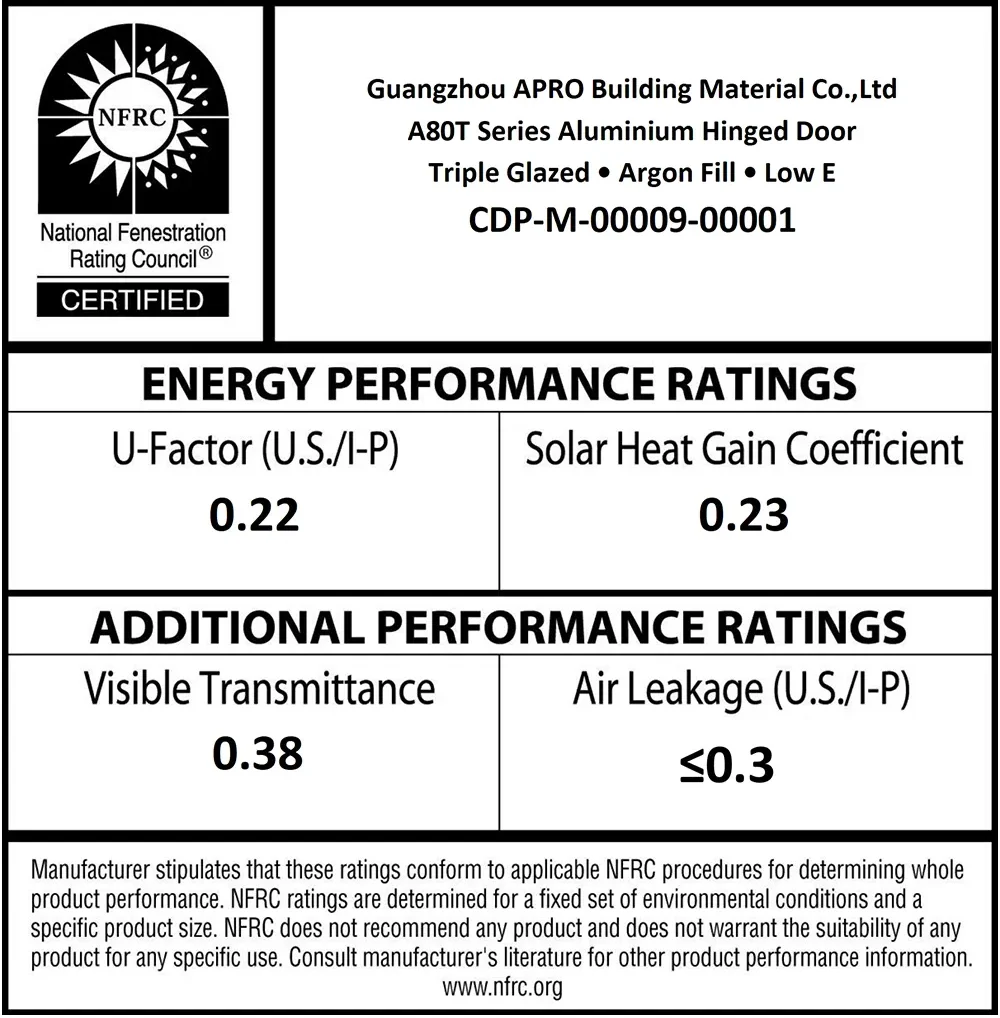
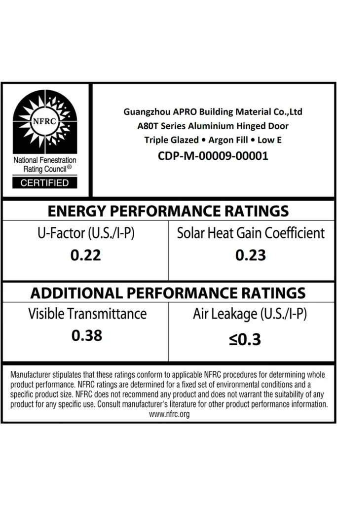
An authentic nfrc window certification label and engineering submittal document reports four primary physical properties tested and modeled under standardized boundary conditions.
“`
+—————————————————————————————————-+
| CORE NFRC ENERGY PERFORMANCE METRICS MATRIX |
|---|
+——————-+———————-+——————–+————————————+
| NFRC Metric | Standard Protocol | Typical Target | Primary Engineering Impact |
|---|
+——————-+———————-+——————–+————————————+
| عامل U | ANSI/NFRC 100 | 0.26 to 0.42 | Measures rate of non-solar heat |
|---|---|---|---|
| (Thermal Loss) | (NFRC 102 Hot Box) | Btu/(h·ft²·°F) | loss; dictates winter heating load |
| SHGC | ANSI/NFRC 200 | 0.20 to 0.40 | Measures fraction of solar heat |
| (Solar Gain) | (LBNL WINDOW 7.8) | (Scale: 0.0 – 1.0) | admitted; dictates AC chiller size |
| Visible Trans. | ANSI/NFRC 200 | 0.40 to 0.65 | Measures fraction of visible light |
| (VT – Daylighting) | (Photopic Response) | (Scale: 0.0 – 1.0) | transmitted; impacts daylighting |
| Condensation Index | ANSI/NFRC 500 | 45 to 70 | Rates resistance to interior glass |
| (CI / CR Rating) | (Temperature Isotherm | (Scale: 1 – 100) | and frame surface condensation |
+——————-+———————-+——————–+————————————+
“`
1. U-Factor (ANSI/NFRC 100)
The U-Factor measures the rate of non-solar heat transfer through the entire window assembly. Lower U-factor numbers indicate superior insulating capabilities.
2. Solar Heat Gain Coefficient (SHGC – ANSI/NFRC 200)
U factor and shgc represent the dual pillars of fenestration energy performance. SHGC measures the fraction of incident solar radiation admitted through a window, both via direct transmission and absorbed heat released inward.
3. Visible Transmittance (VT – ANSI/NFRC 200)
Visible Transmittance measures the amount of daylight in the visible spectrum (380 nm to 780 nm) that passes through the glazing.
4. Condensation Index (CI / CR – ANSI/NFRC 500)
The Condensation Index evaluates a window assembly’s ability to resist the formation of interior surface condensation under specific cold exterior and humid interior conditions. Higher CI values (ranging from 1 to 100) indicate that internal aluminum frame surfaces and glass perimeter edges stay warmer, preventing mold growth and interior drywall water staining.
Cross-reference NAFS structural and air infiltration ratings in our NAFS window performance ratings guide.
Total Window U-Factor (Uw) vs. Center-of-Glass (Ug): The Critical Trap
The single most frequent mistake in commercial fenestration procurement is accepting Center-of-Glass (COG) thermal ratings as proof of whole-window compliance.
“`
+—————————————————————————————————-+
| WHOLE-WINDOW vs. CENTER-OF-GLASS THERMAL DISCREPANCY |
|---|
+—————————+———————————–+————————————+
| Quoted Parameter | Supplier Quoted Value | Actual Certified Whole-Window Value |
|---|
+—————————+———————————–+————————————+
| Center-of-Glass (Ug / COG) | U = 0.20 Btu/(h·ft²·°F) | Misleading; ignores frame bridging |
|---|---|---|
| Edge-of-Glass (Ue) | Unquoted | U = 0.32 – 0.40 (Spacer heat leak) |
| Aluminum Frame (Uf) | Unquoted | U = 0.45 – 0.85 (High conductivity) |
| Total Assembly (Uw) | Claimed “U = 0.20” | Actual Uw = 0.32 – 0.36 (FAILED) |
+—————————+———————————–+————————————+
“`
The Area-Weighted Calculation Formula
In accordance with NFRC methodology and ISO 15099, the total window U-factor (Uw or Ut) is calculated using an area-weighted formula combining three distinct thermal zones:
“`
Uw = [(Uc × Ac) + (Ue × Ae) + (Uf × Af)] / Atotal
“`
Where:
Why Aluminum Frame Thermal Breaks Are Decisive
Aluminum possesses high thermal conductivity (k ≈ 160 W/(m·K)). Without an engineered thermal barrier, heat flows rapidly across the extrusion profile. To achieve certified commercial U-factors below 0.32 Btu/(h·ft²·°F), window systems must incorporate continuous, multi-cavity polyamide insulating struts (PA66 GF25) with widths of 24 mm to 34 mm. APRO’s commercial aluminum series utilizes advanced polyamide thermal breaks and warm-edge spacer technology to eliminate thermal bridging.
Computer Simulation (LBNL THERM/WINDOW) vs. Physical Hot Box Testing
How does the NFRC certify thousands of custom commercial window configurations without physically testing every custom size?
“`
+—————————————————————————————————-+
| NFRC SIMULATION vs. PHYSICAL HOT BOX TESTING |
|---|
+——————-+————————————+——————————————-+
| ميزة | Computer Simulation (THERM/WINDOW) | Physical Guarded Hot Box (NFRC 102) |
|---|
+——————-+————————————+——————————————-+
| Primary Standards | ANSI/NFRC 100 / ISO 15099 | NFRC 102 / ASTM C1363 |
|---|---|---|
| Modeling Tool | LBNL THERM 7.8 & LBNL WINDOW 7.8 | Calibrated climate & metering chambers |
| Core Purpose | 2D finite element thermal modeling | Physical validation of simulation models |
| Turnaround Time | 3 to 7 business days | 3 to 6 weeks |
| Submittal Role | Standard commercial compliance path | Required for initial system certification |
+——————-+————————————+——————————————-+
“`
1. Finite Element Modeling (LBNL THERM)
An authorized NFRC simulation laboratory imports precise CAD DXF cross-sections of the manufacturer’s aluminum profiles. Engineers assign exact thermal conductivities to every material (aluminum alloy 6063, polyamide PA66 GF25, EPDM gaskets, low-E glass coatings, desiccant-filled spacers, and Argon gas cavities). The software runs finite element 2D heat transfer equations, generating visual thermal isotherms that reveal temperature distributions and local heat flux vectors across the frame.
2. Optical and Glazing Calculation (LBNL WINDOW)
The glazing cavity is modeled in LBNL WINDOW using spectral data from the International Glazing Database (IGDB). The program computes exact center-of-glass U-factor, solar heat gain, and optical transmittance based on glass thickness, surface coating emissivity, and gas mixture concentration (minimum 90% Argon).
3. Physical Hot Box Validation (NFRC 102)
To maintain simulation accreditation, NFRC mandates baseline physical validation. An actual full-scale window assembly specimen is mounted between a climate chamber (chilled to -18°C / 0°F) and a metering chamber (heated to +21°C / 70°F) with simulated 12.3 mph (5.5 m/s) dynamic wind. The measured heat loss must correlate within strict tolerances (±10%) of the computer simulation model.
Cross-reference physical laboratory test procedures in our commercial window test reports compliance guide.
How to Audit an NFRC Simulation Report and CPD Number
When reviewing vendor energy submittals, project teams should execute a 5-step engineering audit to confirm document validity.
“`
+—————————————————————————————————-+
| 5-STEP NFRC SUBMITTAL AUDIT CHECKLIST |
|---|
+—+——————————-+———————————–+—————————-+
| # | Audit Action | Verification Item | Pass / Fail Criteria |
|---|
+—+——————————-+———————————–+—————————-+
| 1 | Verify 11-Digit CPD Number | Search NFRC Certified Directory | Listed in active database |
|---|---|---|---|
| 2 | Confirm Licensed Agency (IA) | Check Inspection Agency Stamp | Intertek / Keystone / QAI |
| 3 | Match Extrusion Die Profiles | Compare CAD sections in report | Identical to Shop Drawings |
| 4 | Validate Spacer Technology | Check spacer model & material | Warm-edge spacer confirmed |
| 5 | Verify Gas Fill Concentration | Confirm Argon percentage (>= 90%) | Documented in simulation |
+—+——————————-+———————————–+—————————-+
“`
Step 1: Verify the 11-Digit CPD Number
Every certified product line is assigned a unique NFRC Certified Products Directory (CPD) code (e.g., `APR-M-001-00001-00001`). Procurement managers can input this code directly into the online NFRC CPD database to verify the manufacturer’s licensing status and certified ratings.
Step 2: Confirm Inspection Agency (IA) Sign-Off
A valid NFRC simulation report must be reviewed and stamped by an authorized third-party Inspection Agency (such as Keystone Certifications, Intertek, or QAI Laboratories).
Step 3: Match Extrusion Profiles with Architectural Shop Drawings
Verify that the aluminum profile model numbers, frame depths, and polyamide thermal strip dimensions modeled in the simulation report match the project’s approved architectural CAD shop drawings.
Step 4: Audit Spacer and Sealant System
Spacer type significantly influences edge-of-glass U-factor (Ue). Ensure the simulation reflects the specified warm-edge composite or stainless steel spacer rather than a standard highly conductive aluminum spacer box.
Step 5: Verify Gas Fill Retention
Ensure the simulation specifies a minimum of 90% Argon gas fill. If field specifications require durable thermal performance over a 20-year lifespan, verify that double-sealed IGU construction (polyisobutylene primary seal with silicone secondary seal) is documented.
Cross-reference full CSI Section 08 submittal package preparation guidelines in our window and door submittal package guide.
Climate Zone Specification Guide: IECC & ASHRAE 90.1 Compliance
Model energy codes divide North America into 8 distinct climate zones, establishing prescriptive thermal thresholds for commercial fenestration.
“`
+—————————————————————————————————-+
| COMMERCIAL WINDOW NFRC CODE REQUIREMENTS (IECC / ASHRAE 90.1) |
|---|
+——————-+—————————-+———————–+—————————+
| IECC Climate Zone | Representative Cities | Max Whole-Window U-Fac | Max Assembly SHGC |
|---|
+——————-+—————————-+———————–+—————————+
| Zone 1 (Very Hot) | Miami, Honolulu | يو <= 0.45 Btu/h·ft²·°F | SHGC <= 0.23 (Solar Domin) |
|---|---|---|---|
| Zone 2 (Hot) | Houston, Phoenix, Orlando | يو <= 0.40 Btu/h·ft²·°F | SHGC <= 0.25 |
| Zone 3 (Warm) | Atlanta, Dallas, Las Vegas | يو <= 0.34 Btu/h·ft²·°F | SHGC <= 0.25 |
| Zone 4 (Mixed) | New York, Seattle, D.C. | يو <= 0.32 Btu/h·ft²·°F | SHGC <= 0.35 |
| Zone 5 (Cool) | Chicago, Denver, Boston | يو <= 0.28 Btu/h·ft²·°F | SHGC <= 0.38 |
| Zone 6 (Cold) | Minneapolis, Toronto | يو <= 0.26 Btu/h·ft²·°F | SHGC <= 0.40 |
| Zones 7-8 (Subarc) | Anchorage, Calgary | يو <= 0.22 Btu/h·ft²·°F | No SHGC Limit (Passive) |
+——————-+—————————-+———————–+—————————+
“`
Southern Cooling Climates (Zones 1–3)
In hot southern regions, cooling loads dominate commercial building energy consumption. Fenestration specifications prioritize low SHGC (≤ 0.23 – 0.25) paired with spectrally selective Low-E coatings on Surface #2 (inside face of the exterior pane) to reflect solar infrared radiation before it enters the building envelope.
Northern Heating Climates (Zones 5–8)
In cold northern regions, reducing conductive winter heat loss is paramount. Specifications mandate ultra-low whole-window U-factors (≤ 0.26 – 0.28 Btu/(h·ft²·°F)). Achieving these thresholds requires deep thermal breaks (> 30 mm), triple-pane glazing units, or argon/krypton gas fills, with Low-E coatings positioned on Surface #3 to reflect interior room heat back inside.
How APRO Delivers Certified Thermal Performance for Commercial Projects
APRO’s engineering and technical team provides turnkey thermal modeling and fenestration manufacturing for energy-efficient commercial buildings:
# FAQ
What is the difference between Energy Star and NFRC ratings?
NFRC (National Fenestration Rating Council) is the independent scientific organization that establishes test standards and calculates exact physical ratings (U-factor, SHGC, VT, Condensation Index). Energy Star is an EPA voluntary labeling program that sets regional qualification thresholds based on NFRC certified data. For commercial construction, building inspectors enforce NFRC certified simulation data directly against IECC / ASHRAE 90.1 building codes.
Why is whole-window U-factor higher than center-of-glass U-factor?
Aluminum framing and glass perimeter spacer edges conduct heat much faster than the center of an insulated glass unit. The whole-window U-factor (Uw) is an area-weighted average that incorporates the conductive heat loss of the frame (Uf) and edge-of-glass (Ue), making the whole-window U-factor higher (less insulating) than the center-of-glass rating (Uc).
What is a good NFRC U-factor for commercial aluminum windows?
For commercial thermally broken aluminum windows, a whole-window U-factor between 0.28 and 0.34 Btu/(h·ft²·°F) (1.59 to 1.93 W/(m²·K)) is considered high performance for double-glazed units. Triple-glazed commercial assemblies with deep thermal breaks can achieve U-factors between 0.18 and 0.24 Btu/(h·ft²·°F).
Can custom commercial window dimensions be NFRC certified?
NFRC publishes standard model test sizes in its Certified Products Directory (CPD) for consistent comparison across manufacturers. For commercial architectural projects with non-standard opening sizes, certified simulation laboratories generate project-specific component modeling simulations (LBNL THERM/WINDOW) based on approved NFRC algorithms and validated physical hot box calibrations.
How does Low-E coating placement affect NFRC SHGC and U-factor ratings?
In an insulated glass unit (IGU), placing the Low-E coating on Surface #2 (inside face of the exterior pane) maximizes solar heat reflection, producing a lower SHGC ideal for cooling climates. Placing the Low-E coating on Surface #3 (exterior face of the interior pane) allows solar radiation to enter while reflecting interior room heat back inside, optimizing winter thermal retention in heating climates.
What should project buyers confirm before requesting a quotation for nfrc window certification?
Project buyers should confirm project geographic location, IECC climate zone, specified maximum whole-window U-factor and SHGC targets, frame thermal break depth requirements, glass build-up specifications, and rough opening dimensions.
# Conclusion / What to Do Next
Achieving strict energy code compliance and thermal comfort on commercial building projects requires disciplined verification of whole-window NFRC certified data. General contractors and procurement teams that demand complete LBNL THERM simulation submittals avoid expensive code rejections, thermal condensation failures, and unexpected HVAC plant resizing.
Recommended Project Actions:
1. Review project mechanical and architectural specifications to identify required whole-window U-factor and SHGC limits under IECC / ASHRAE 90.1.
2. Require shortlisted suppliers to provide authentic NFRC computer simulation reports (THERM / WINDOW) rather than center-of-glass brochures.
3. Verify that proposed aluminum profiles incorporate multi-cavity polyamide thermal breaks and warm-edge spacer technology.
4. Partner with an experienced engineering fabricator like APRO to receive certified thermal simulation modeling and comprehensive submittal support.
# CTA
For engineering review and thermal simulation support on your commercial window and door project, contact APRO. Submit your architectural elevations, window schedules, and energy specifications to our technical team for preliminary thermal modeling review and competitive quotation documentation.
# Suggested Image Ideas
1. LBNL THERM 2D Isotherm Cross-Section: A colorful finite element thermal simulation graphic showing temperature isotherms and heat flux vectors traveling through a thermally broken commercial aluminum window profile.
2. Whole-Window vs. Center-of-Glass Thermal Diagram: An engineering diagram illustrating the three distinct thermal zones of a window assembly: Center-of-Glass (Uc), Edge-of-Glass (Ue), and Aluminum Framing (Uf).
3. NFRC Energy Performance Label Anatomy: A technical breakdown of an official NFRC rating label highlighting U-Factor, SHGC, Visible Transmittance, and Condensation Index metrics.
# Suggested Internal Links
# Schema Suggestions
# Notes / Cautions